We build a sense of trust.

NOVELIC is the world's premier provider of mmWave radar solutions, embedded engineering design services, and semiconductor design services.NOVELIC provides chip design services, specializing in millimeter-wave/AMS circuits, high-voltage ICs, digital ASIC design services and front-end systems, as well as FPGA development services.NOVELIC is an advanced perception systems company.Aside from automotive radar sensors, we also offer advanced solutions for software-defined vehicles

Certifications

ISO 9001:2015
ISO 27001
Serbia Serbia
Veljka Dugosevica 54, Belgrade, Belgrade 11000
+381116558794
Germany Germany
Moosacher Straße 82, Munchen, Bavaria 80809
Romania Romania
Bucuresti Sectorul 2, Strada Daomna Ghica Nr. 83, Bloc 63, Bucuresti, Bucuresti 010011
Macedonia Macedonia
Bulevar Partizanski Odredi 63-1, Skopje, Skopje 1000
NA
50 - 249
2012

Service Focus

Focus of Engineering Services
  • Electrical Engineering - 80%
  • Mechanical Engineering - 20%
Focus of Testing Services
  • Automation Testing - 20%
  • Smoke Testing - 10%
  • Performance Testing - 10%
  • Unit Testing - 15%
  • Integration Testing - 15%
  • System Testing - 20%
  • Regression Testing - 10%

NOVELIC's exceptional IoT Development services give clients a considerable advantage over the competition.

Industry Focus

  • Automotive - 50%
  • Industrial - 20%
  • Consumer Products - 10%
  • Healthcare & Medical - 10%
  • Transportation & Logistics - 10%

Client Focus

50% Medium Business
5% Large Business
45% Small Business

Detailed Reviews of NOVELIC

No Review
No reviews submitted yet.
Be the first one to review

Client Portfolio of NOVELIC

Project Industry

  • Transportation & Logistics - 33.3%
  • Automotive - 33.3%
  • Healthcare & Medical - 33.3%

Major Industry Focus

Transportation & Logistics

Project Cost

  • Not Disclosed - 100.0%

Common Project Cost

Not Disclosed

Project Timeline

  • Not Disclosed - 100.0%

Project Timeline

Not Disclosed

Clients: 21

  • Fernride
  • Liebherr
  • VBG
  • Interventional Systems
  • Afry
  • ZF
  • MicroMate
  • Infineon
  • In-Cabin Monitoring Radar
  • Battery Management System
  • End of Line testing
  • Power Electronics
  • Analog IC Design
  • Short-Range Radar Sensor
  • ECU Data Logger
  • DSP
  • Embedded Firmware
  • Embedded hardware
  • PCB Design
  • Sensor fusion
  • ADAS

Portfolios: 3

mmWave Radar Sensors for Jackknife Warning and Coupling Guidance

mmWave Radar Sensors for Jackknife Warning and Coupling Guidance

  • mmWave Radar Sensors for Jackknife Warning and Coupling Guidance screenshot 1
  • mmWave Radar Sensors for Jackknife Warning and Coupling Guidance screenshot 2
  • mmWave Radar Sensors for Jackknife Warning and Coupling Guidance screenshot 3
Not Disclosed
Not Disclosed
Transportation & Logistics

Client Overview

VBG Coupling Systems is a part of VBG Group, an international engineering group founded in 1951 with more than 1800 employees in 16 countries. The company is the leader in its segment of the transport industry in the Nordics and the United Kingdom and a pioneer in developing trailer coupling systems utilizing the latest technology.

The Problem

VBG Coupling was looking to build an innovative product – VBG Driver Assist – that would help truck drivers couple trailers and reduce the risk of damage or injury. The company needed a technology that would provide reliable and accurate sensing around the backside of the truck and help the driver navigate the vehicle with ease and precision.

Challenge #1 – Jackknifing

Jackknifing is one of the most common types of truck accidents that occurs when the front vehicle skids but the trailer attached to it does not slow down or stop. This causes the trailer to push the towing vehicle to the side or spin it around until it faces the trailer backwards. When the driver loses control of the vehicle, it can lead to serious damage, injury, or death.

The existing warning systems will only activate after jackknifing has occurred. There is no warning beforehand to alert the driver that jackknifing is about to happen and help them avoid it.

Challenge #2 – Coupling Guidance

Typical coupling assistance systems have a rear camera that helps the driver couple the trailer. Since there is only limited visual information available, the driver often has to step out of the cabin and check if the truck is at the correct height for coupling, which is a time-consuming process.

Camera lenses get dirty from rain, dust, or mud and require regular cleaning. Cameras become unreliable in reduced visibility conditions caused by the elements or poor lighting.

The Solution

Our team of radar experts has proposed a solution that would solve both the jackknifing and coupling challenges. NOVELIC was involved in all the steps from PoC to the final product, providing system design, data processing algorithms, hardware and software development, as well as enclosure design.

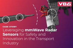
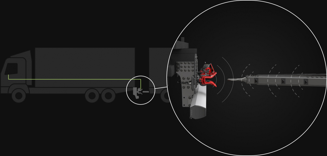
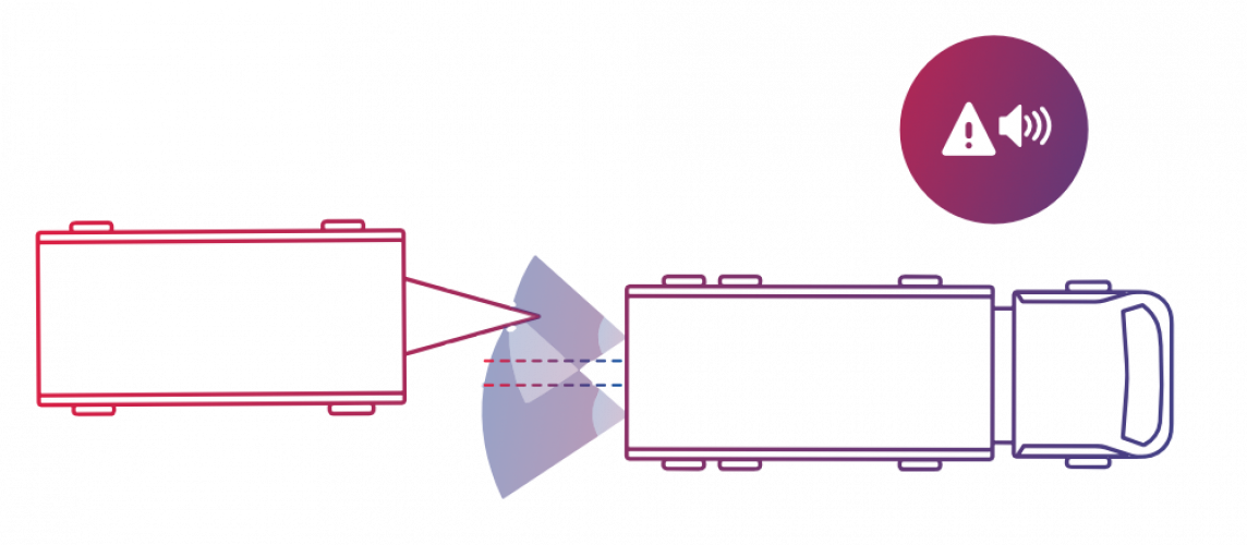
The solution is based on 79 GHz mmWave radar sensors placed on the back of the truck. The sensors send electromagnetic waves that reflect off the passive corner reflectors placed on the trailer and the data processing of the returning signal allows for precise calculations of the drawbar position in 3D space (distance, horizontal, and vertical angle). This data is sent to the truck environment via a CAN bus, triggering sound alerts and providing display information (to be realized in the near future). All signal processing is done in the sensor module, so no external processing is needed.

When the angle between the trailer and the truck reaches a critical value, a sound alarm will alert the driver that there is a risk of jackknifing. The audio signal is triggered at an angle of 40 degrees and increases in frequency the closer the rig is to the jackknife angle. This provides the driver with enough time to react and avoid jackknifing.

”Right from the start of the development project we had a good engagement. Of course we had some challenges during the way but the goal was clear for both parties. Novelic gave us good support and they also felt a sense of urgency when it was needed. The end product is now delivering a great functionality, so we are very satisfied with the collaboration.”
– VBG Group Truck Equipment

The coupling guidance system gives the driver precise direction and distance instructions for coupling. There is no need for the driver to leave the cab and visually inspect the drawbar position, which makes the coupling process faster and more efficient.

Since radar waves pass through non-conductive materials, the sensors can be completely covered in mud or dirt and work with 100% reliability. Radar sensors are not influenced by light, so they will work in pitch dark or sun glare. The radar casing has an IP69K rating, meaning the sensor is dustproof, resistant to high temperatures, and can withstand high-pressure washdown.

Design of a Miniaturized 60 Ghz FMCW Radar Sensor For Short-Range Applications

Design of a Miniaturized 60 Ghz FMCW Radar Sensor For Short-Range Applications

  • Design of a Miniaturized 60 Ghz FMCW Radar Sensor For Short-Range Applications screenshot 1
  • Design of a Miniaturized 60 Ghz FMCW Radar Sensor For Short-Range Applications screenshot 2
Not Disclosed
Not Disclosed
Automotive

Markets that rely on sensors, such as industrial, automotive, and consumer electronics, are heavily competitive. Sensor cost, size, and performance are the key deciding factors that dictate the overall price and quality of the end product. mmWave radar technology allows contactless measurement of close-proximity objects while significantly reducing module size and price. This project aimed to develop a 60 GHz FMCW radar sensor that would operate under heavy space restraints and synthesize extremely steep, wide-band, and highly accurate frequency chirps, which are indispensable in modern high-resolution short-range applications.

Challenges

The development of the 60 GHz FMCW radar sensor faced multiple design constraints:

  • Compact design
    • The sensor needed to operate in a very small form factor (32 mm × 22 mm × 7 mm), limiting the space available for antennas, electronics, and the enclosure.
  • High Precision Requirements
    • The radar system had to detect objects with sub-2 cm spatial resolution and support very steep frequency slopes to detect objects at close proximity, less than 20 cm away.
  • Power Efficiency
    • The radar module was required to deliver over +17.5 dBm effective isotropic radiated power while maintaining low power consumption, dissipating only 690 mW.
  • Wide chirp bandwidth
    • The design demanded chirp bandwidths of up to 10 GHz to enhance spatial resolution while minimizing flicker noise, pushing the radar’s modulation rate to over 200 MHz/µs.

The Solution

High-performance radar transceiver

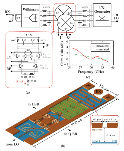
At the core of the radar sensor is a fully integrated FMCW transceiver chip developed using SiGe BiCMOS technology. This technology enabled the incorporation of a frequency synthesizer and analog baseband circuitry in a compact chip, allowing high integration in a small package.

High spatial resolution with steep frequency slopes

The radar transceiver supports chirp bandwidths up to 10 GHz, enabling sub-2 cm spatial resolution for precise detection. To detect objects at close ranges, the module achieved high modulation rates exceeding 200 MHz/µs, creating steep frequency slopes essential for accurate measurement in short-range applications.

Low power consumption and heat management

Despite its high performance, the radar sensor consumes just 690 mW, which is crucial for maintaining low heat output and efficient operation. The module is encased in a small aluminum housing to help manage heat and protect sensitive components.

Precise signal processing

The baseband processor provides programmable gain and filtering, enabling flexible operation. The system features a programmable gain amplifier (PGA) and active-RC filters, allowing the radar sensor to handle a wide range of radar beat frequencies with adjustable filtering capabilities. The overall gain is programmable up to 60 dB.

The developed radar sensor was tested with corner reflectors placed at distances of 20 cm and 22 cm. The radar system successfully measured these targets using 10 GHz bandwidth chirps with a modulation rate of 240 MHz/µs. The results demonstrated sub-2 cm spatial resolution, as predicted by simulations.

Additionally, the effective isotropic radiated power (EIRP) was measured using a horn antenna, and the module’s output power was consistent with expectations across the full frequency range. The system’s linearity surpassed that of comparable radar sensors in the 60 GHz band, ensuring reliable performance for short-range applications.

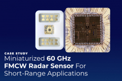
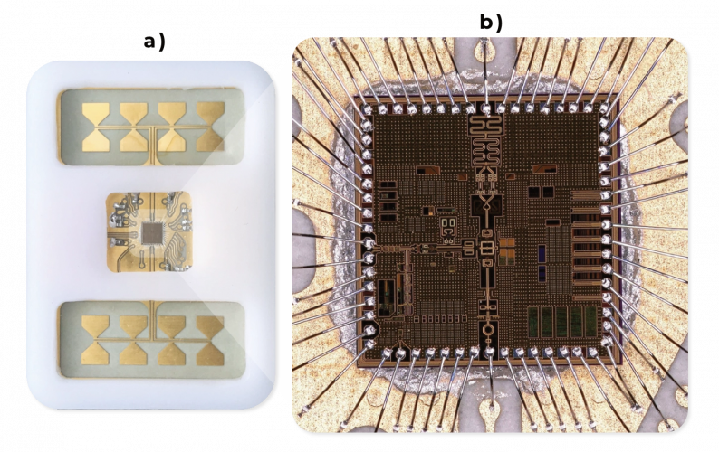
The team had created a prototype 60 GHz sensor that integrates mmWave FMCW radar capabilities. The design leverages an advanced frequency generation system with a circuit board featuring embedded antenna arrays. What made this development notable is its compact form factor and cost-effective manufacturing potential, achieved through careful design choices and affordable materials. The performance remains competitive, featuring industry-leading 10-GHz sweep ranges and 240-MHz/μs modulation capabilities. This positioned the device as a promising candidate for widespread adoption in short-range radar applications.

NOVELIC offers design services for AMS, RF, and mmWave integrated circuits, including related layout services. Our know-how in signal processing HW, high-speed RF transmissions, and firmware development makes an essential difference and brings a competitive advantage to our customers.

Enabling Firmwareless Motorized Medical Arm Position Control

Enabling Firmwareless Motorized Medical Arm Position Control

  • Enabling Firmwareless Motorized Medical Arm Position Control screenshot 1
Not Disclosed
Not Disclosed
Healthcare & Medical

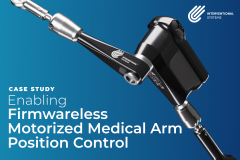
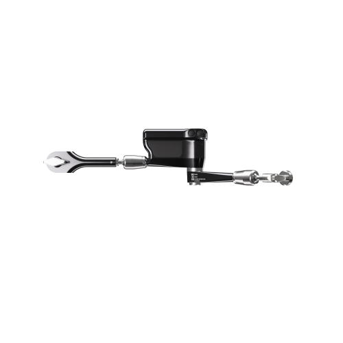
Interventional Systems is a medical equipment manufacturer resonsible for Micromate™ – a robotics platform for micro-invasive interventions. They were designing an articulated medical arm for interventional radiologists and oncologists that could hold surgical equipment in a fixed position. This would remove the need for manual holding, reduce physical strain on the medical experts performing procedures, increase patient safety, and reduce intervention time.

Challenges

With patient safety as a priority, there were numerous limitations in the way the project could be realized. The device could not be powered directly by an outlet, as to not create an electrical hazard and/or harm to patients. No physical connector (such as a USB port) could be used, in order to prevent the device from getting damaged due to contact with liquids or disinfectants used in the operating room.

Since every part of a medical device needs to undergo a rigorous certification process, it was extremely complicated to have any kind of software to operate the motor. Finally, due to the articulated arm’s size, there were significant constraints on the dimensions of the battery, motor, and electronics.

Button-operated position locking

Once the robotic arm is placed in the desired position, it needs to be safely locked into place. This requires manually tightening a wing bolt on the arm’s joint. To avoid this, the client wanted to enable locking and unlocking the arm by simply pressing a button.

For maximum patient safety and to avoid accidentally pushing a button, the design requires two buttons on the sides of the device to be simultaneously pushed to lock or unlock the arm.

Following a minimalist design, there are two sets of buttons on the sides along with a multicolor LED light that indicates the state of the device (charging, locked, unlocked, low battery, etc.).

A firmwareless solution

The motor turning the bolt needs to provide a certain amount of torque to lock a joint and is powered by the battery. Typically, this kind of system would be controlled by a microprocessor running custom-written software. Due to the solution being a part of a medical device, if the hardware were software-controlled, the software itself would have to pass the certification process.

To avoid this time-consuming, complex, and costly option, NOVELIC took on an unconventional approach by designing a discrete electronics circuit able to control the motor without any software.

Wireless charging

Plugging devices directly into a power outlet should be avoided in the operating room. With the additional requirement of the device having no connectors, our team set out to design a wireless charging cradle.

The cradle communicates with the device using the Qi protocol, an interface standard for wireless power transfer using inductive charging. The cradle itself can be charged anywhere outside the operating room through a power adapter. A fully charged battery allows for at least 30 locking and unlocking cycles between recharges.

Size limitations

The number of required lock/unlock cycles between charges is dictated by the battery capacity, which in turn dictated its size. To fit the battery, motor, and the electronics inside the arm, our team used a Rigid-Flex PCB with bending abilities as a method of stacking PCBs, which helped overcome the space constraint.

Risk analysis and medical certification

NOVELIC performed a thorough risk analysis of all possible scenarios that could lead to patient’s harm (device malfunctioning, overheating, not charging properly, etc.). During the precertification process, our team ensured that the device does not transmit or receive electromagnetic signals above the defined limits. The lithium battery was certified at a battery manufacturer to obtain the UN/DOT 38.3 certification that allows air transportation. Finally, the whole device was certified in the United Kingdom to ensure compliance with IEC 60601-1:2005+AMD1:2012, including relevant national deviations.

Highlights

  • Easy-to-use arm positioning
  • Firmwareless control
  • Wireless charging
  • Small dimensions​